Creating the Starch Pasting Cell Geometry in TRIOS
Setting the Geometry Details
To set up the SPC geometry in TRIOS software:
- In TRIOS software, access the Geometries section of the File Manager and click the New
 icon. The Welcome to New Geometry Wizard screen displays; click Next.
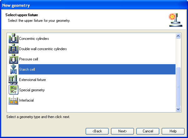
- Select the Starch cell from the geometry list, then click Next.
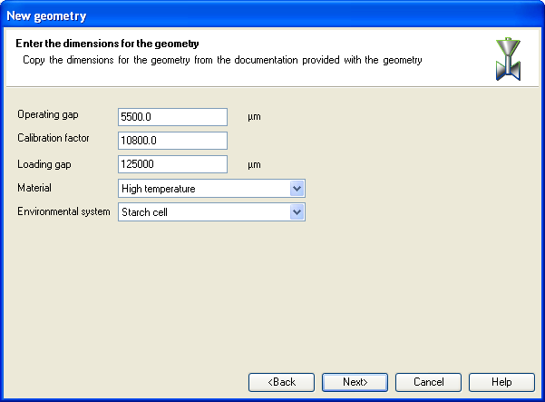
- Enter the dimensions for the geometry and click Next when finished:
- The Operating gap is the clearance between the underside of the impeller and the bottom of the cup, at the measuring position. The instrument can only set this gap if a reference position has been found (see Finding the Zero Point below). The default value of 5500 µm is recommended if no other information is available.
- The Calibration factor is used in the conversion from instrument parameters, i.e., torque and angular velocity, to sample viscosity. The viscosity is given by:
Viscosity = Calibration factor x
Torque/Angular Velocity
Where the units of viscosity are Pa.s, torque units are N.m, and angular velocity units are rad.s-1. The units of the calibration factor are thus m-3. This factor may be determined by following the instructions in Calibration of the Measuring System Factor.
The default value of 10800 m-3 was determined by TA Instruments' engineers, and should be used if no other information is available.
- Select the type of Material being tested.
- Verify that Starch cell is the Environmental system being used.
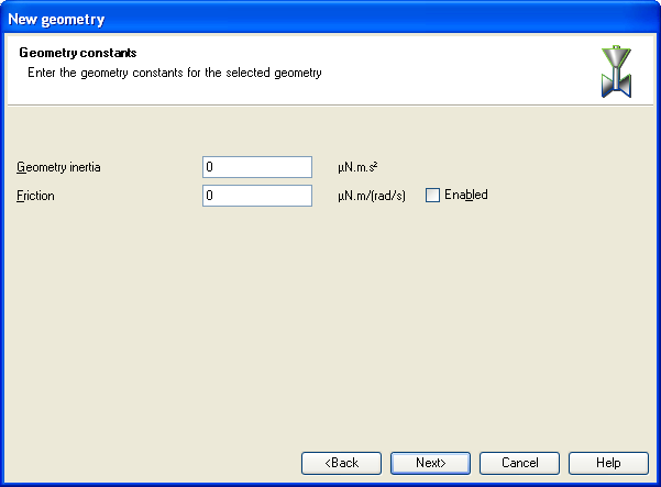
- Enter the constants for the geometry and click Next when finished:
- Geometry inertia
- Friction
- Enter the geometry Name and, if desired, Notes. When satisfied with your field entries, click Next, then Finish. This completes SPC geometry setup.
Setting Up the Conical Rotor
The SPC may also be used as a conventional concentric cylinder rheometer, with the conical hard anodized rotor, part number 545761.001.
To set up this geometry:
- Access the Geometries section of the File Manager and click the New icon. The Welcome to New Geometry Wizard screen appears; click Next.
- Select the Concentric cylinders from the geometry list, then click Next.
- Enter the details as:
- Stator inner diameter (mm): 37
- Rotor outer diameter (mm): 31
- Cylinder immersed height (mm) 37.00
- Gap (mm): 5920
Back to top
Finding the Zero (Datum) Point
For the instrument to set the correct geometry gap, a zero point reference position must first be found. This can be done using the Zero gap button on the rheometer touch pad. Note that the gap of
5 mm recommended for the starting point of the automatic routine occurs when the upper surface of the impeller evaporation prevention ring is about
5 mm below the upper surface of the assembled Starch Cell.
The zero point should be determined at the beginning of each session.
Back to top
Bearing Friction Correction
The friction due to the rheometer air bearing is negligible except when very low viscosity samples are used, and no correction is normally necessary when using the Starch Cell. However, if you do wish to introduce a correction for bearing friction, the procedure is available through the instrument control software. See DHR/AR Rheometer Instrument Calibrations > Instrument Inertia for more information.
Back to top
Rotational Mapping
Rotational mapping is used on the TA Instruments' DHR Series and AR Series Rheometers to ensure optimal performance for very sensitive samples. It should not normally be necessary with the Starch Cell, but may be used if very precise data are required at low angular velocities. See DHR/AR Rheometer Instrument Calibrations > Rotational Mapping for more information.
Back to top
